WayKeeper™: an offline Linux archive for the forearm. Two distinct builds. One measured path from parts to field use.
PRE-BUILD / HARDWARE VALIDATION PENDING
Start here: scope, source revision and build comparison
WayKeeper™ Field Manual
INIT.WTF / Bench edition 1.0 / 12 September 2026
Build an offline archive you can carry on your forearm. Choose RUGGED, the fixed-screen Rev 0.2 route, or FOLED, the experimental flexible-AMOLED Rev 0.1 route. Both use a small Linux computer, physical controls, a local archive, a wrist bridge battery and a larger vest battery.
This manual translates the repository's design documents into an ordered build and verification plan. It is a pre-build manual, not a report of an assembled or tested device. No hardware measurements, completed CAD, qualified wiring schematic, driver integration or successful physical prototype are claimed here. Commands have been checked against the retrieved source; this editorial pass did not compile or run the complete application. Record the results as you build.
Read the right revision
The source is Rali0s/WayKeeper, frozen at commit b13d317fb698318cc409eab7bad57c9387df5e67. The relevant directory is Fallout-Assistant/docs/DIY/. The software builds from Fallout-Assistant/, not the repository root. The source's shared power/thermal specification takes precedence over conflicting runtime estimates in either build specification. R1, R2, R3, R4
The original Markdown specifications remain the design record. Procedures labelled integration work below are proposed ways to complete missing engineering. A screenshot, rendering or attractive concept board is not evidence of physical performance. Specifications printed inside concept artwork may disagree with the written bill of materials; use the text and the exact manufacturer's documentation for the purchased revision.
Decision
RUGGED / Rev 0.2
FOLED / Rev 0.1
Display
Fixed 3.5-inch IPS, 640 × 480
DFR1262 6.67-inch flexible AMOLED kit
Touch
Module supports touch; application integration to test
No touch; physical controls required
Wrist power
UPS HAT (C) + compatible 1000 mAh cell
PiSugar 3, 1200 mAh
Main challenge
Power margin, small-screen input and wearable fit
Display compatibility and unqualified repeated folding
Shell target
120 × 105 × 32 mm
117 × 84 × 32 mm closed; about 168 × 84 mm open
Source budget
$350–450 base; $420–550 with mirror/spares
$630–700 base; $700–800 with mirror/spares
First milestone
Stable desktop terminal
Stable flat-display terminal
Prices are source planning allowances, not current checkout totals. Shipping, tools, compatible cells, adapters, reprints and controller work can change them substantially. Measure every received component before CAD.
What is established, and what remains to build
In the repository: a C++ ANSI interface, local library and card workflows, map resources, tests, and platform deployment materials. Design intent: the wearable package, full power integration, physical controls, tamper hardware and foldable cassette. The broader architecture's model-serving and large-computer ideas are not the 512 MB wrist baseline. Start with models disabled and deterministic local retrieval. R5, R6, R7, R8
The Bluetooth interface does not establish a working BitChat link: transmit is locked in the reviewed implementation. Likewise, a Sentinel screen lock is not proof of encrypted storage. Sensor labels in artwork do not establish the presence of GPS, radiation instruments or other installed sensors. Publish only the functions demonstrated by your actual assembly.
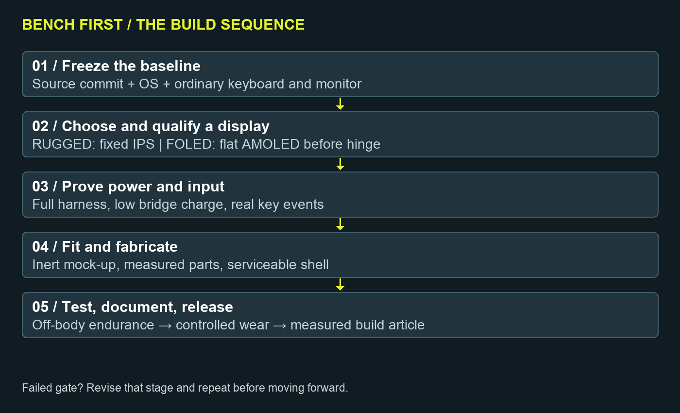
The build order
Inventory the parts and preserve their documentation.
Boot the Pi and run the software with an ordinary keyboard and monitor.
Qualify the selected small display on the bench.
Validate the complete power path, including the long sleeve cable and bridge battery.
Integrate the compact controls and test every required action.
Fit an inert mock-up, then fabricate a serviceable enclosure.
Complete off-body endurance and shutdown tests before wearing powered hardware.
Capture measurements, failures and repair procedures for the final article.
At each gate, keep the failed result as well as the fix. A manual becomes reproducible when another builder can see which revision actually passed.
RUGGED / Fixed-screen build
Build A / Rev 0.2 / Recommended first prototype
RUGGED uses a recessed fixed display and a removable electronics stack. Its practical advantage is that the screen has no folding mechanism. The initial deliverable is a reliable desktop assembly; the wearable enclosure follows measured dimensions and power results. Primary design source: R1.
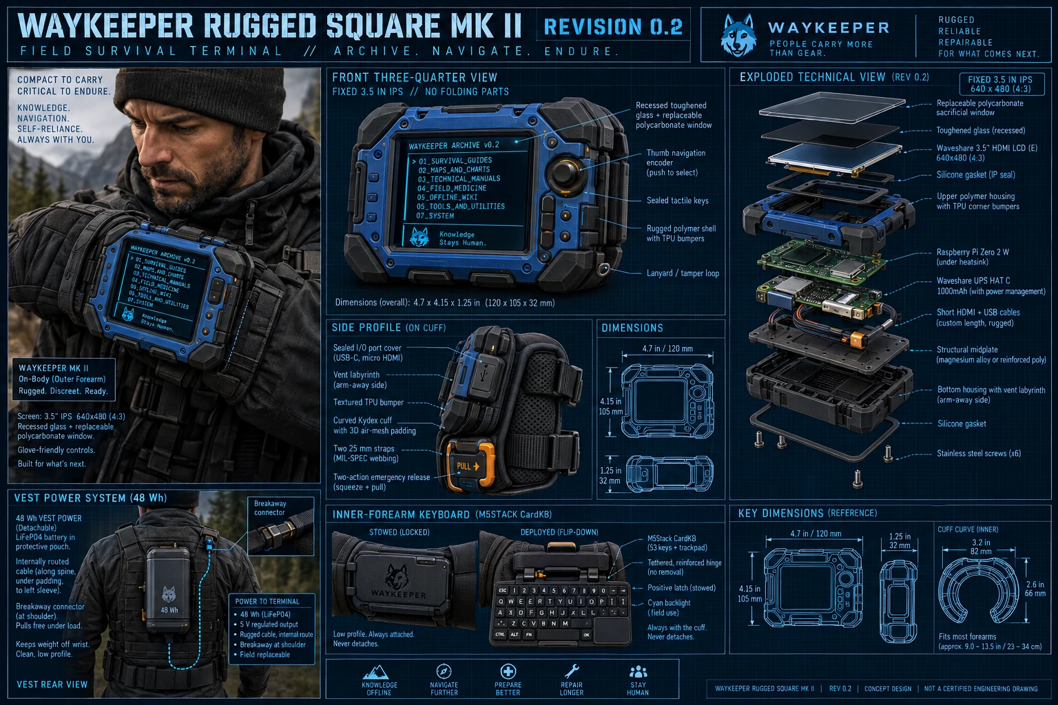
Repository concept illustration, not a build photograph or fabrication drawing. Its battery chemistry, keyboard/trackpad depiction and some protection details are illustrative. The specified CardKB is a 50-key I²C keyboard, without the pictured trackpad. Do not infer an IP rating or select battery chemistry from this image.
A1. Purchase in two stages
Buy the desktop electronics first. Delay final shell printing and custom cable lengths until those electronics pass. Use a 32–64 GB test card if available; move to the 256 GB archive after the software and storage layout are stable.
Item
Quantity
Requirement / purchasing check
Raspberry Pi Zero 2 W
1
512 MB; correct headers and standoffs for the UPS stack
Waveshare 3.5inch HDMI LCD (E)
1
SKU 21915, 640 × 480; do not substitute a similarly named SPI panel
Waveshare UPS HAT (C)
1
Check board revision, connectors, supplied standoffs and documentation
Compatible bridge cell
1
3.7 V / 1000 mAh design basis; verify inclusion, polarity, protection and connector against HAT documentation
microSD
1 + mirror
256 GB archive target; reliable supplier; verify capacity and restore
CardKB v1.1
1
I²C keyboard; plan a Linux input bridge and logic-level verification
ANO navigation encoder + I²C adapter
1 each
Product 5740 is the adapter; confirm the encoder is also in the order
Sealed shortcut switches
4–6
Menu, back, home, display, lock and a deliberately assigned sixth function
Short mini-HDMI to HDMI lead
1
Match connector orientation and include service loop clearance
USB OTG arrangement
1 set
Required if using USB touch or a USB keyboard bridge; prevent VBUS backfeed
Signal harness
1 lot
Labelled connectors, level shifting where required, strain relief
Protected V50 vest pack
1
48 Wh design basis; use the specified always-on 5 V output
Sleeve power harness
1
Source starts at 1.5–2 m of 22 AWG; qualify voltage drop under load
Inline fuse + holder
1
Source proposes 2 A near the pack; validate against load and cable rating
Guarded breakaway + switch
1 each
Accessible deliberate release; recessed master control
Cuff materials
1 lot
1.5–2 mm Kydex, two 25 mm straps, anti-rotation strap, spacer mesh, EVA pads
Shell hardware
1 lot
Polymer shell, midplate, standoffs, inserts, TPU bumper, removable film
The source's $13.95 navigation allowance must cover the actual encoder and adapter selected. Do not treat a bare adapter listing as a complete control. The bridge battery also needs its own receipt line if the HAT is sold without it. M3, M4, M6
Bench tools: multimeter, USB power meter, suitable protected 5 V supply, soldering tools, insulated work surface, calipers, scale and thermometer. A current-limited bench supply and oscilloscope improve diagnosis of inrush and rail dips. Add crimp tools for the chosen connectors; avoid mixing visually similar connector families.
A2. Prove the screen and computer
Install Raspberry Pi OS Lite 64-bit on the test card. Create your own login and a documented recovery method. Run the shared software procedure before attaching custom controls.
With power removed, connect the Pi's mini-HDMI output to the display's HDMI input. Supply the display as its exact revision requires. Start with short bench wiring.
Boot at an EDID-supported mode and record the actual output. Establish a legible 640 × 480 console before designing the screen opening.
Check the application's documented 80-column baseline with an 8 × 16 console font, which gives approximately 80 × 30 characters at 640 × 480. A larger 10-pixel-wide font yields 64 columns, but that smaller layout must be tested for clipping; it is not automatically supported.
Exercise menus, search, map navigation, help, long filenames, errors and the on-screen keyboard if used. Photograph the worst case, not just the attractive home screen.
Connect touch using one chosen supported interface. Verify Linux events and the application's response independently. USB enumeration alone does not make a raw Linux console touch-aware. Keep physical keys available throughout.
Modern Raspberry Pi OS display configuration uses KMS. Read the current Pi documentation and the panel's revision-specific guidance; do not paste several old Pi 3/4/5 overlays into a Zero 2 W installation. Preserve a bootable backup before editing display settings. M1, M2, M3
Gate A-screen: readable interface, repeatable cold boot, correct orientation, complete navigation with a standard keyboard, and a recorded decision about touch. If touch remains unfinished, list it as unfinished and build around physical input.
A3. Qualify the power assembly
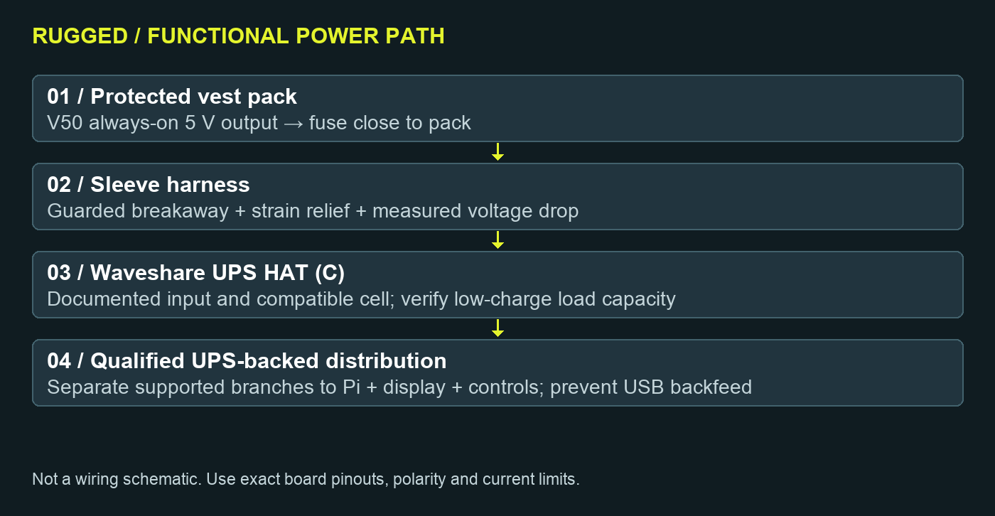
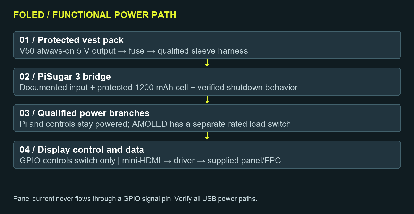
Functional routing only. This is not a pin-level wiring schematic. The exact HAT revision, power terminals, battery polarity and USB power topology must be documented before fabrication.
Inspect the HAT and cell before connection. Confirm cell connector polarity electrically; connector fit is not proof of polarity. Fit the manufacturer-specified spacers so the battery and exposed contacts cannot contact the Pi or metal midplate.
Establish the UPS-backed 5 V distribution using documented terminals. Both Pi and display must remain powered during a vest disconnect if uninterrupted visible operation is a requirement. Do not use a GPIO signal pin to supply the display.
Measure Pi + display + input load with the bridge charged, then while it is recharging. Charging current consumes input headroom in addition to the operating load.
Repeat with a partly depleted bridge. The HAT vendor describes output capability falling as battery voltage falls; a full-charge test alone cannot qualify the complete load. The design's 6–8 W transient estimate corresponds to roughly 1.2–1.6 A at 5 V before charging and conversion losses. R3, M4
Add the actual sleeve harness, fuse, breakaway and connectors. Measure voltage at the load, not only at the vest pack. Inspect for warm connectors and reboot or undervoltage indications.
Perform ten loaded disconnect/reconnect cycles with recovery between them. Record bridge state, load, display state, minimum observed voltage and any kernel or application fault. Then test orderly low-battery shutdown separately.
If the UPS cannot support the selected combined load at low charge, stop at the bench. Revise the power architecture or load before packaging. Do not bypass cell protection, parallel regulated outputs or rely on a larger fuse to cure an overloaded converter.
A4. Integrate the controls
Use the shared input worksheet. CardKB is not a drop-in USB keyboard: its I²C bytes need translation to Linux/application key events. A dedicated microcontroller presenting USB HID is one possible integration route; a reviewed Linux input service is another. Neither is supplied as a proven hardware solution by this manual.
Bring up one device at a time. Verify SDA/SCL idle voltage before connecting the Pi, assign addresses, then test simultaneous use. Map rotary movement to scrolling, directional presses to navigation and the center press to selection. Keep Back and Home independently reachable. Test held keys, repeat, modifier combinations, disconnect recovery and startup ordering.
Build the optional five-key chord rail only after the ordinary keys work. Five binary keys allow 31 non-empty combinations mathematically; this is not evidence of a usable trained typing system. Start with a small printed mapping and an explicit chord-release/debounce rule.
Gate A-input: complete an offline search, open and exit a document, pan a map, recover from a wrong menu and shut down without the bench keyboard.
A5. Fit, fabricate and assemble
The written target is 120 × 105 × 32 mm, with an approximately 72 × 55 mm opening. Published display PCB dimensions are 76.6 × 63.6 mm, and active area 70.68 × 53.36 mm. These are layout inputs; connector protrusion and cable bend clearance determine the real enclosure. R1
Weigh every bare part. Target total forearm mass is 390–550 g; the source gives a 600 g prototype ceiling. Shipping weight is not component weight.
Make a cardboard or foam mock-up with inert ballast. Check wrist flexion, elbow clearance, coat sleeves, typing and release. Wear the inert assembly for 60 minutes; stop for pressure, tingling, numbness or restricted movement. Adjust the saddle rather than tightening straps to suppress rotation.
Form a separate open Kydex saddle using appropriate forming tools, away from the body and electronics. Start from the source's roughly 165 × 115 mm saddle blank and trim to the wearer. Do not make a locked rigid ring around the arm.
CAD the measured stack. Use approximately 2–2.5 mm polymer walls and a 1–1.5 mm aluminum or 2 mm G10 midplate as starting dimensions. Insulate metal from circuitry. Keep battery compression, screw tips and sharp edges out of the cell compartment.
Support the display through its documented mounts. Recess the glass about 2.5–3 mm below the TPU bumper plane. Screws must not clamp glass. Fit a replaceable film; make a rigid storm cover removable and test touch sensitivity if one is used.
Place vents away from skin and make the liner washable and removable. A gasket and vent labyrinth do not establish waterproofing. Leave service access for the microSD, display, battery and cable connectors.
Put CardKB on a tethered inner-forearm plate with a protected stowed latch and a trial opening angle around 20–35°. Check strain relief through the full hinge travel. Prevent the keyboard from pressing into the wrist when closed.
Route the vest cable with shoulder and elbow service loops. Place the guarded breakaway at the shoulder/upper arm and test release with an inert assembly before using it with electronics.
A6. Release gates
Gate
Procedure
Record / pass condition
Desktop endurance
4 hours representative use
No unexplained reset or undervoltage; readable display
Bridge operation
10 loaded vest swaps
No reboot; reserve and recovery recorded
Fit
60 minutes inert wear
No pain, numbness or circulation restriction; easy removal
Powered endurance
12 hours attended off-body on suitable supply
Stable temperatures, logs and storage; not a V50 runtime claim
Wear
1 hour indoors, then 2-hour controlled walk
Stop for heat, cable snag, skin symptoms or mechanical movement
Serviceability
Remove and replace display/control module
No destructive adhesive or broken strain relief
Source screening targets include 25 release operations, 500 strap cycles and 1,000 keyboard-hinge cycles. Record the method and failures. If doing a 0.5 m drop screen, begin with an unpowered dummy over a rubber surface, off the body. Moisture screening belongs on an unpowered assembly, followed by inspection and drying. These exercises do not confer an IP, impact or personal-protection rating. R1
FOLED / Flexible-AMOLED build
Build B / Rev 0.1 / Experimental display cassette
FOLED keeps the large flexible display concept as a separate build. Its first success criterion is a working flat display, keyboard and power system. A flexible panel is not necessarily rated for repeated folding. Do not build the final hinge around a guessed radius. Primary design source: R2.
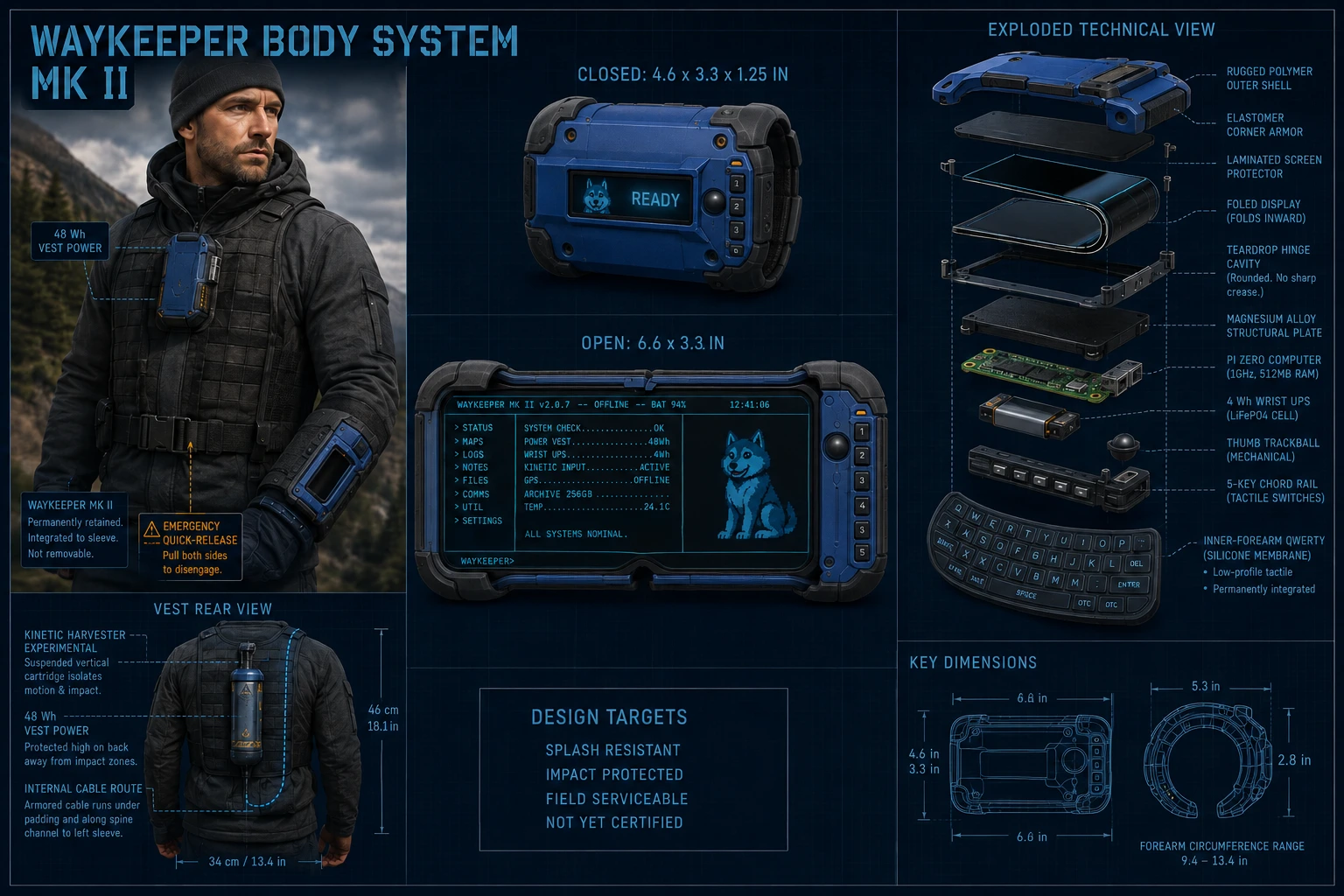
Repository concept illustration. The depicted fold, sensors, battery chemistry and retained mounting are design ideas. This image supplies neither a dynamic bend rating nor a proven thermal, electrical or mechanical design. The actual DFR1262 kit has no touch input.
B1. BOM and procurement gate
Reuse the shared Pi, archive, CardKB, navigation and vest-power plan. FOLED substitutes the display and wrist UPS, adds a display power switch, and may add a closed-state status OLED. Do not buy both wrist UPS designs for one assembly unless intentionally comparing them on separate benches.
Item
Quantity
Requirement / purchasing check
Pi Zero 2 W + storage
1 + mirror
Raspberry Pi OS Lite 64-bit; 512 MB baseline
DFRobot DFR1262 flexible AMOLED kit
1
6.67-inch panel, HDMI driver, MIPI adapter and correct FPC
PiSugar 3
1
1200 mAh version for Pi Zero; confirm exact battery/board revision
CardKB + input bridge
1 each
Physical typing is mandatory; display has no touch
Measure actual parts, cable travel and wearable mass
The source estimates $630–700 for a self-printed one-card build, $700–800 with mirror/spares and $800–950 with outsourced fabrication. A qualified custom foldable display/controller can take the project above $1,000. These are planning ranges, not supplier quotes. Optional generator hardware is outside the base budget. R2
Before ordering a folding assembly, obtain the panel supplier's answers in writing: static minimum bend radius; dynamic minimum bend radius; allowed bend zone and direction; permitted support/adhesive method; cycle life at that radius; connector/FPC bend limits; humidity constraints; and warranty exclusions. If no dynamic rating is available, keep the panel flat or within its documented static curvature and label the folding feature unresolved.
The alternative Gesight BF051FBM-AK0 in the source is a MIPI-DSI module requiring a controller quotation. It is not an electrically interchangeable HDMI kit. A nominally similar size does not make it a drop-in replacement.
B2. Establish a flat display baseline
Manufacturer information for DFR1262 specifies a 2400 × 1080 SPR panel, 50 Hz, approximately 3 W typical consumption and no touch. Its dedicated controller power connection is 5 V micro-USB. Preserve the supplied driver/adapter/FPC arrangement and handle it according to the vendor's instructions. M7
Inspect and photograph the panel, connector locks and FPC before power. Use a supported flat fixture that does not load the active area or connector tail.
Power down both devices before fitting FPC or HDMI. Use the exact connector orientation in the supplied documentation; never force a latch or hot-plug the bare panel tail.
Prove the complete kit on a known-compatible video source. Record the accepted HDMI mode and image orientation before attributing problems to the Pi.
Connect the Zero 2 W and test a supported input mode. Its usual maximum output width is 1920 pixels; the panel's 2400-pixel native width is therefore a compatibility question, not a promised configuration. Find a stable mode/scaling arrangement and photograph text quality. M1, M2
Test the Linux console itself. Vendor desktop setup screenshots do not demonstrate a working Lite/TTY installation. Record the usable character grid, aspect ratio, clipping and reconnect behavior.
Measure load at bright and dark interface states, during boot and during mode changes. An AMOLED's content-dependent draw makes a single attractive dark screen an incomplete power test.
Gate B-display: repeated cold boots and readable, complete interface at a recorded mode using physical keys. Do not fabricate a hinge until the panel/controller/Pi combination works in the flat fixture.
B3. Power and closed-state behavior
Functional diagram, not a circuit schematic. The controller receives power through a rated branch; a GPIO controls a switch and does not supply panel current. Switching and USB backfeed behavior need bench verification.
PiSugar 3 replaces the RUGGED HAT. Its published maximum 5 V current is a component limit, not proof that the full harness and assembly can continuously deliver that current. The 1200 mAh cell represents roughly 4.44 Wh nominal at 3.7 V; this is short bridge capacity, not all-day power. M8
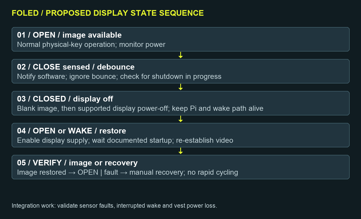
Integration work: implement and test a closed-state sequence. A sensor event is debounced; the application is notified; the display is blanked; the dedicated display branch is turned off only if the controller supports that sequence. The Pi remains powered. On opening or a physical wake key, restore controller power, allow its documented startup interval and re-establish video. Determine actual delays experimentally and record them; do not invent fixed timing.
Test sensor bounce, a disconnected sensor, a stuck sensor, wake during shutdown and loss of vest power while closed. Preserve a hardware-accessible wake/recovery action. Configure a safe default that avoids rapid power cycling and leaves an operator recovery path. A dark status OLED must not be the only indication of a running hot computer.
If the status OLED is fitted, label values according to actual data. Do not display fictional GPS, radiation, power or tamper readings because they appear in concept art. Validate the OLED's bus address against the PiSugar, encoder and CardKB before connecting them together.
B4. Build the cassette only after supplier approval
Measure the panel, driver boards and connector stack in the proven flat fixture. The source's closed 117 × 84 × 32 mm and open approximately 168 × 84 mm envelopes are targets; do not squeeze the driver/FPC to hit them.
Build a removable cassette that carries loads through its frame. Keep fasteners, grit and sharp edges away from the active film. Make the expensive panel replaceable without destroying the cuff.
Make a dummy flex strip and hinge fixture first. Use the supplier-approved bend region and radius to define a rounded path, hard stops and clearance. Do not crease the panel or assume a teardrop shape alone protects it.
Support the FPC separately so it cannot pull on the display connector through travel. A cable that survives opening once may still fail in repeated motion.
Cycle the empty mechanism and inspect interference. Only then use a sacrificial or approved panel specimen. Stop immediately for delamination, pixel lines, flicker, discoloration, cracks or increased hinge force.
Document screen protection and sweat exclusion. This module is not a weatherproof wrist assembly. A flexible film cover or adhesive can change bend behavior; obtain material compatibility guidance before lamination.
Fit the keyboard and cuff using an inert mock-up. The source suggests a keyboard opening angle around 15–25°. The 250–350 g wrist mass is an optimistic target, not a measured outcome. Weigh the completed assembly and revise retention before powered wear.
B5. Qualification ladder
Gate
Required evidence
If it fails
Flat video
Pi model, OS, mode, controller revision, photographs
Resolve display compatibility before hinge work
Power
Peak/average load, low-bridge result, ten vest swaps
Redesign power path or reduce load
Closed state
Repeatable blank/off/wake and fault recovery
Retain manual display control until fixed
Hinge authorization
Supplier dynamic radius, zone and life data
Keep flat/static; no folding claim
Mechanical screening
Fixture dimensions, force observations, image tests
Inspect and redesign before more cycles
Wearability
Mass, skin contact, release and heat records
Change geometry or move mass to vest
Inspection points at 100, 1,000 and 10,000 cycles are a proposed qualification plan from the source, not an existing panel guarantee. Choose a test endpoint consistent with the supplier's limits, and publish the actual number completed. Never sacrifice the only working display merely to claim a large round number.
B6. Optional harvesting remains a separate experiment
The source sketches a suspended generator with a 1–3 W target. That output is unverified and excluded from runtime calculations. Keep batteries stationary; use separate mechanical mass and a guarded fixture. Before any connection to an energy-storage system, qualify regulation, reverse-current protection and compatibility with its documented charging input. Do not wire a generator into raw lithium cells or bypass the pack's charger. Measure stored watt-hours over a timed trial, then compare them with the weight, heat and effort added. R2, R3
SHARED BENCH PROCEDURES / BOTH BUILDS
Shared / Software and controls
S1. Freeze a reproducible baseline
Use a workstation to prepare the source and a Pi-specific Raspberry Pi OS Lite 64-bit card for the wrist computer. The repository's image builder targets Orange Pi Zero 2 / H616; it does not establish Raspberry Pi Zero 2 W support. QEMU validation of a virtual machine also does not validate physical display, GPIO, battery or boot firmware. Do not flash an Orange Pi image to a Raspberry Pi. R5, R8
Record the OS image name, checksum, date, kernel, firmware, source commit and all local patches. Keep the first bootable card intact as a recovery baseline. A workstation binary must match the Pi architecture and linked libraries; copying an x86 executable to the Pi is not deployment.
For a Debian-family build environment, the starting dependency set is build-essential, cmake, ninja-build, git, pkg-config, libgdal-dev, libsqlite3-dev and poppler-utils. Check the pinned CMake files and package availability on your chosen OS. This is a source-based starting list, not a tested fresh-image installer.
The presets use JSON schema version 6, which requires CMake 3.25 or newer, even though the project's declared minimum says 3.21. Confirm cmake --version before using the presets. R6, M10
On a 512 MB Pi, reduce build parallelism to one if memory pressure kills the compiler. Confirm tests were discovered and actually ran; an empty test run is not a pass. Preserve configure/build/test output with the machine architecture. Models are disabled by the reviewed prod preset. Leave them off for the wearable baseline.
S2. Desktop acceptance before appliance boot
Use a conventional keyboard and a terminal at least 80 columns wide. Test the home screen, help, library retrieval, one reviewed card, document return path and map navigation. Repeat with networking disconnected. Separate a missing document/index from a display or keyboard problem by testing on the ordinary monitor first.
Then repeat on the target display at its recorded character grid. Save screenshots or photographs of long text, narrow layouts, errors and navigation. Source evidence of other screen sizes is useful reference material, but your selected font and physical panel still need validation.
S3. Make an appliance after the interactive build works
The repository's image installer demonstrates this layout: executable at /usr/local/bin/waykeeper; cards, library, maps and root RES assets under /opt/waykeeper; mutable state under /var/lib/waykeeper; and a wrapper running waykeeper ui. Its Lite service uses a dedicated waykeeper account and tty1. R8
Integration procedure for Raspberry Pi OS: adapt that layout deliberately after the local binary passes. Create a dedicated service user with a free UID/GID; do not copy the image script's fixed UID 1000 onto an existing Pi installation. Stage the required assets, set read permissions, give the service ownership of its state directory, and verify the executable's shared-library dependencies. Review the wrapper and service unit before installing them.
Keep a working maintenance login and recovery console before assigning tty1. Test manual launch as the intended service user first. Only then enable a reviewed systemd unit, resolve its getty conflict and reboot. Confirm a clean boot, log location, orderly stop and successful recovery if the app exits repeatedly. The repository installer also makes distribution/package and image-cleanup changes; it is not a general-purpose setup script to run unreviewed on your working Pi.
S4. Input integration worksheet
Device
Interface / source address
Required verification
CardKB v1.1
I²C, 0x5F
5 V module supply; confirm signal levels and bridge to key events
ANO adapter
I²C, default 0x49
Encoder included; use compatible logic voltage, debounce and mapping
UPS HAT (C)
Revision-specific I²C
Confirm address, occupied pins and actual telemetry protocol
PiSugar 3
Documented 0x57 / 0x68
Revision/configuration, RTC and battery services; check collisions
Host configuration, driver, events and application handling
For a conventional Pi I²C1 connection, the usual header signals are GPIO2/SDA on physical pin 3 and GPIO3/SCL on physical pin 5, with ground available at pin 6. Confirm the exact board pinout and HAT allocation before wiring. Keep a diagram that distinguishes physical pin numbers from GPIO numbers. Do not connect a 5 V pull-up domain directly to Pi GPIO. M1, M5, M6, M8
Add each peripheral separately, measure bus idle voltage, and record its address. Keep I²C short inside the terminal; the sleeve cable is for power, not an assumed reliable long I²C bus. Duplicate addresses require an actual address change, bus separation or a suitable multiplexer. A successful scan does not prove an input driver.
Define one mapping table and place it in the enclosure service notes. At minimum cover Up, Down, Left, Right, Enter, Escape/Back, Home, help, search, map entry, display wake and orderly shutdown. Provide confirmation for destructive functions. Confirm startup with an absent peripheral, a held key and a disconnected/reconnected keyboard.
S5. Archive and maps
Keep original documents, generated candidates and reviewed cards distinct. Preserve title, source URL, retrieval date, rights/license, checksum and review status. The PDF-to-cards workflow should produce reviewable material, not silently promote extracted or generated text to trusted guidance. R7
The repository has a 50-state map workflow. Its storage profile reports about 580 MiB extracted for Full and 383 MiB for Lite at the reviewed revision, so maps alone do not justify 256 GB. The larger card is an archive allowance. Map Full/Lite packages and platform Full/Lite images are separate choices. R7, R9
Use the selected package's actual checksum manifest and extraction instructions. Verify checksums from the directory intended by that manifest; do not rename files first. Open known locations, check state selection and boundaries, then repeat offline. A map display is not proof of live location: document the actual location source, if one is fitted.
Keep a separately verified mirror. Test recovery by booting the spare card and opening a known document and map. Copying live mutable state without a consistency plan can produce a poor backup. Preserve user notes separately, and record whether a mirror was made from a clean shutdown.
S6. Privacy, tamper and optional interfaces
The reviewed code's lock behavior must not be described as proven disk encryption. If private storage is required, design and test that partition, key handling, mount/unmount and recovery path separately. Do not trigger destructive erasure from an unqualified cuff switch. Test tamper events initially as logged events and ordinary locks. R5
UART exploration is optional and separate from the wearable's base acceptance. Use only equipment you own or have authorization to inspect, an appropriate logic-level adapter and the repository's UART documentation. TTL UART is not RS-232. Verify voltage before wiring, do not feed adapter VBUS into an already powered target, and begin with a deliberate read-only test. Any transmit test needs the correct port and an understood target. A loopback on your own adapter is a suitable first functional test. R10
Bluetooth status and a named collaboration workflow do not prove a working messaging transport. Keep external communication claims out of the article until both endpoints and actual messages have been demonstrated.
Shared / Power, heat and recovery
P1. Define the measurement boundary
The shared design uses a nominal 48 Wh vest pack and plans on approximately 38–42 Wh delivered to the load, an assumed 80–88% usable fraction. These are estimates. Measure the selected pack, output port, cable, converters and duty cycle as an assembly. The source identifies the V50's always-on 5 V USB-A path; do not assume its USB-C PD behavior is equivalent. R3, M9
Use watt-hours rather than comparing battery mAh ratings at different voltages. A 1000 mAh, 3.7 V cell is about 3.7 Wh nominal; it is not a 5 Wh supply. If your meter measures delivered output energy, do not apply the same conversion loss a second time.
energy (Wh) = voltage (V) × capacity (Ah)
runtime (h) = delivered usable energy (Wh) / mean load (W)
mean load = sum(state power × fraction of time in that state)
voltage drop = load current × complete loop resistance
P2. Planning examples, not runtime promises
RUGGED state
Source load estimate
Runtime from 38–42 Wh
Active display
4.5–6.0 W
About 6.3–9.3 h
Dim display
3.5–4.8 W
About 7.9–12 h
Display blanked
1.5–2.5 W
About 15.2–28 h
The wide range is deliberate: it combines energy and load extremes. For a concrete example, assume 40 Wh delivered and 25% active at 5.25 W, 25% dim at 4.15 W and 50% blank at 2 W. Mean load is 3.35 W, giving 11.9 hours. This calculated scenario is not a measured mixed-use result.
The source's rounded mixed-use runtime table is a planning shorthand. Multiplying its load intervals by that 25/25/50 duty split gives 2.75–3.95 W rather than a uniquely determined 3.2–3.8 W. Use the measured duty cycle and report the arithmetic explicitly. FOLED has its own active/off loads; do not reuse the RUGGED dim-state value for it. R3
For a nominal 3.7 Wh bridge at a 5 W load, assuming 80% delivery gives about 36 minutes. A nominal 4.44 Wh bridge gives about 43 minutes under the same assumptions. Actual reserve depends on cell health, converter cutoff, peak load and temperature. Measure reserve near the intended shutdown threshold, not only from full charge.
P3. The sleeve cable is part of the circuit
The source begins with 1.5–2 m of 22 AWG wire and a 2 A fuse. Those choices need load testing. For an illustrative measured/assumed complete loop resistance of 0.21 ohm, a 1.6 A load loses 0.34 V and dissipates 0.54 W in the loop. At 2 A that becomes 0.42 V and 0.84 W. Connectors and the fuse add resistance. This example uses a resistance assumption, not a certified value for every 22 AWG harness.
Measure the actual complete harness at operating current. Increase conductor size, shorten the path or revise distribution if the Pi rail loses margin. Do not increase voltage beyond any connected module's specification. A fuse protects against faults; it does not regulate voltage or make a thin cable adequate. Label polarity at every detachable connector and guard conductive breakaway contacts against shorts.
The V50's per-port limit and the UPS's available output are separate constraints. The RUGGED HAT's low-cell capability and charging load are especially important. Keep radio-on, display-bright and bridge-recharging cases in the test matrix even if normal use is lighter. M4, M9
P4. Set up orderly shutdown
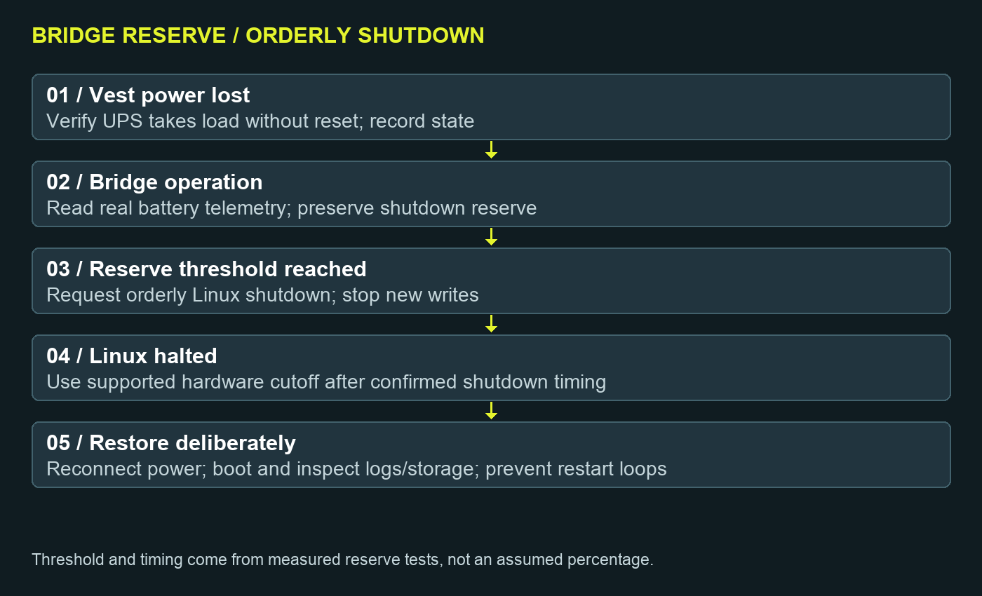
Integration work: hardware telemetry must feed a tested policy. A parser or UI battery field alone is not a shutdown controller. Determine how the chosen board reports battery status, how shutdown is requested, how long storage flush takes, and how hardware removes power after Linux halts. Use the vendor-supported mechanism for the exact board revision.
On the bench, measure at least three discharge runs at the worst credible operating load.
Determine the interval between a proposed trigger and the earliest unsafe rail/cutoff condition.
Choose a reserve that exceeds observed shutdown time plus an explicit margin for cold cells, aging and variation. Write down the chosen values; do not borrow an arbitrary percentage from another battery.
Test vest loss while idle, while opening a document and while writing a disposable note. Inspect logs and the filesystem after restart.
Test power returning during shutdown. Prevent a restart loop or a half-completed shutdown. Confirm deliberate recovery from the fully off state.
Keep a verified spare card and backup before intentionally testing power-failure recovery. Do not repeatedly yank power from a mounted working archive as a substitute for a controlled shutdown test.
P5. Temperature and charging
Charge the protected packs off-body in a dry, attended setup during prototype work. Keep the cells away from screw points, crush loads, heater surfaces and moving generator masses. Do not use the wearer as a heatsink. Fit temperature measurement at the cell, regulator/UPS region and skin-facing shell; record ambient temperature and method.
The V50 lists charge cutoff limits of 0–45°C. The repository proposes a five-degree margin, yielding a 5–40°C planning charge envelope. These are pack-specific values, not certification of the complete cuff. Its discharge limits and the panel's component temperature ratings do not establish a whole-device operating range. R3, M9
Measure with the actual liner, closed shell and representative clothing; open-bench cooling can hide a problem. Stop for abnormal heat, odor, swelling, unstable power or skin discomfort. A cool CPU reading does not prove a cool battery or safe contact surface.
Optional solar belongs after the wired system passes. The source's approximate direct-sun charging times are planning estimates, not all-day weather guarantees. Use the pack's documented charging input and record actual harvested Wh. Shade, orientation and load while charging change the result.
Shared / Test record and Hackaday package
T1. One record per physical revision
Use the supplied build-log.md, measurements.csv and bom.csv templates. Give every change a revision: shell, harness, display/controller, cell, software commit and input mapping. A runtime result is meaningful only when its configuration is recoverable.
Test
Minimum useful evidence
Completion criterion
Source/build
Commit, OS, architecture, compiler/CMake and test output
Successful compile; non-empty test suite results recorded
Display
Cold boot video, accepted mode, character grid, worst-case text
All required controls/content visible
Input
Mapping, voltage/address sheet, task completion video
No unexplained reset; source and load within measured limits
Recovery
Trigger, shutdown duration, cutoff, restart and filesystem check
Repeatable orderly shutdown and usable recovery
Thermal
Ambient, cell, regulator and skin-side measurements
Stable temperatures within the chosen component envelope
Mechanical
Measured CAD, mass, release and cable travel
Serviceable assembly; fit and emergency removal demonstrated
FOLED hinge
Supplier limits, fixture, cycle count, before/after image test
No folding claim without corresponding evidence
Archive
Manifest, known-file tests, mirror boot
Offline content and restore demonstrated
Run at least three comparable runtime trials. Keep the same starting charge, temperature, brightness, radio policy and interaction script. Report minimum, maximum and individual observations, not only the best run. Calibrate the energy estimate and aim to explain deviations exceeding the source's 10% check. A slow USB meter can miss brief transients; identify its sampling limitations.
T2. Troubleshooting from symptoms
Symptom
First checks
Next action
Reboots when vest cable is removed
Bridge charge, load rail, display sharing and HAT current
Test shorter harness and lower load; qualify UPS near low charge
Reboots while bridge charges
Pack/port limit and combined charging + running input
Measure total input; revise qualified charge/load policy
Black HDMI panel
Correct connector, dedicated power, accepted mode and EDID
Prove on known-compatible source, then re-test Pi
Touch enumerates but does nothing
Console vs graphical input path
Integrate event handling or use physical controls
CardKB visible but no typing
Voltage domain, address, byte reader and key-event bridge
Test one layer at a time with bench keyboard recovery
FOLED fails after closing
FPC strain, bend path, switch sequence
Stop cycling; inspect flat and compare original image tests
Application restarts continuously
Service paths, permissions, assets and environment
Stop service and run manually as service user
Archive opens only online
Missing files, paths, index or package
Verify local manifest, restart offline, test known documents
Short runtime
Measurement boundary, brightness, radio/load, cell health
Compare state-by-state Wh; do not extrapolate from mAh
T3. Build log sequence
Why a wearable archive? State the use case and why offline physical controls matter. Show both concepts but identify the actual build selected.
The first bench boot. Publish the exact Pi, OS, source revision and ordinary-monitor test.
The display decision. Show text legibility, mode and touch/input findings. For FOLED, show the flat fixture and supplier response.
Where the watts go. Show the complete harness, measurement boundary, bridge behavior and failed attempts.
Making the controls real. Explain the CardKB bridge, mappings and one-handed task test.
From foam to enclosure. Share measured dimensions, mass, material, inserts, service access and iteration photos.
Wear and repair. Show release, cable routing, thermal observations and module replacement.
What survived. Publish test data and actual shortcomings, then release the matching build instructions and files.
T4. Image and process-flow shot list
The included concept boards explain intent. Replace or accompany them with real photographs as the build progresses: parts laid out with labels; bare display dimensions with calipers; flat bench wiring; fuse and breakaway; meter at the specified boundary; low-battery shutdown capture; input adapter close-up; foam fit trial; separated enclosure layers; service hatch; worn front/side view; and the repaired/revised failure point.
For FOLED, add an open/closed sequence, FPC routing, a radius fixture with its measurement, supplier-approved bend zone, and cycle-counter evidence. Never caption a rendered image as a working prototype. Keep personally identifying logs, private notes and location coordinates out of published screenshots unless deliberately included.
Export diagrams as editable SVG plus PNG. These manual diagrams show functional flow, not final circuitry. Before releasing build instructions, add your verified wiring schematic with connector numbering, polarity, conductor sizes, fuse, voltage domains and power-switch details. Add STEP/STL files, print settings and a measured drawing corresponding to the tested shell revision.
T5. Draft the eventual project page
Suggested title: WayKeeper: an offline Linux field terminal for the forearm.
Short description: A DIY wearable archive with physical controls, local reference material and maps, a small Linux computer and a vest-to-wrist bridge-power system. RUGGED uses a fixed IPS display; FOLED explores a flexible AMOLED cassette.
Pre-build project introduction: “WayKeeper is my attempt to put a useful offline reference library within reach without depending on a phone connection. This project documents two hardware directions: a fixed-screen RUGGED terminal and a flexible-display FOLED experiment. I am starting with a bench prototype, measuring the power and input system, and publishing the revisions as they become repeatable.”
Keep that future-facing language until results exist. After building, replace it with the actual configuration and evidence: assembled mass, measured delivered Wh, runtime under a defined workload, display mode, software commit, input implementation, repair time and unresolved limitations. Do not claim both variants are completed if only one is built.
Hackaday.io is a suitable project log location. Populate Details, Components, Files, Project Logs and Build Instructions with your actual artifacts. Hackaday's editorial tip page recommends a descriptive subject and a project page with pictures and details; a tip is a request for editorial consideration, not a guaranteed feature. M11
Post-build tip template:
Subject: WayKeeper: [tested variant] offline forearm terminal

Project: [public project URL]
Build files: [public repository/release URL]

I built [actual configuration] to [specific use case].
The interesting engineering problem was [problem], solved by
[implemented approach]. I measured [result, method and conditions].

The project page includes photographs, wiring, build instructions,
the bill of materials, test data and what did not work.
A short demonstration is here: [video URL].
The bracketed fields are intentional blanks for your future build results. No pitch has been sent and no hardware completion has been asserted.
T6. Publication and rights check
Preserve the repository license and attribution with redistributed code. The reviewed repository includes MIT licensing and separate license-status documentation; third-party archive material and imagery still require their own rights review. A public GitHub file does not automatically grant every possible reuse right. Record image provenance, permission/license and captions in the release. R11
Use WayKeeper™ as the project styling requested here; this manual makes no claim of registered trademark status. Release the manual as a pre-build bench edition until the measured results are incorporated. Keep a change log that shows which guidance was replaced after assembly.
Source register
Repository links are pinned to the reviewed commit. Manufacturer documentation was consulted on 12 September 2026 and can change; archive the revision supplied with your purchased hardware. Reference tags in each chapter point here. The procedures combine repository requirements with editorial integration and test guidance, explicitly marked where implementation remains open.
The five functional diagrams were authored for this manual from the cited design and integration discussion. They are editable explanatory graphics, not fabrication drawings. Concept artwork is reproduced from the user-requested project for this bench edition; confirm image reuse rights before a public release.